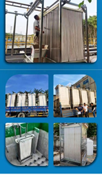
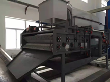
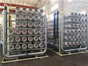
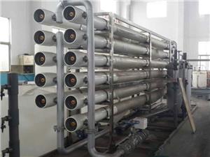
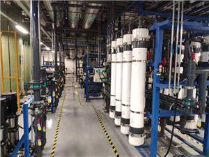
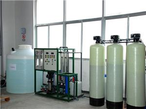
Waste water treatment plant
Waste water treatment plant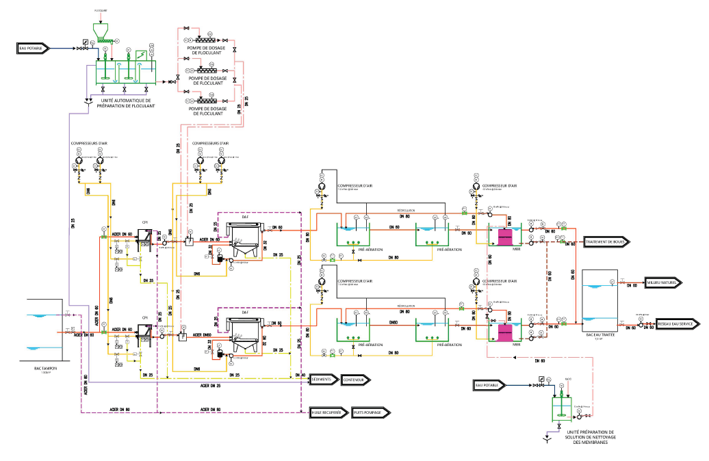
1.1. GENERAL CONSIDERATIONS
In this chapter we present a summary of the basic data established for the elaboration of the
project, which constitute the basis for the design of the wastewater treatment plant (now
referred to as STEP).
Thus, in the next paragraphs we again present the design flow rates considered, as well as the
design parameters adopted for the sizing of the STEP (including piping and pumping).
1.1.1. Design flow rates
The STEP will have two (2) parallel treatment lines for the liquid phase. The design flow rate
considered is 5 m 3 / h.
In normal situation, the two lines will operate with a flow rate of 2.5 m3 / h per each line.
Note that the equipment and pipes of each line have been sized for a maximum flow rate of
5.0 m3 / h.
Thus, in a situation where a line is out of service (for reasons of breakdown, maintenance,
etc.), it is possible to treat all of the effluent with a single line running, so as to allow
continuous operation. (24/7, if possible) from the station.
2.1.1. Design pollutant loads
As part of this project, on November 15, 2017, samples of contaminated water from the drain
lines of reservoirs 4A8 and P21, in the TMN and TNIS, respectively, were collected,
upstream of the foot separators (API) of bac.
Samples of contaminated water from the drain lines of reservoirs 4A8 and P21, in the TMN
and TNIS, respectively, were collected, upstream of the foot separators (API) of bac and
based on the results referred to above, together with the reference values collected in the
specialized bibliography, it was possible to define the pollutant loads considered for the
sizing of the STEP equipment. The values adopted are presented in the following table.
Table 1. Pollutant loads for the design of the treatment plant
Settings Unit
Values
considered
pH 6.5-8
Suspended Solids (MES) mg / l 200
Oils and Greases (O&G) mg / l 300
Chemical Oxygen
Demand (DOC) mg / l 2,200
Biochemical Oxygen Demand mg / l 1,100
It is noted that the color and suspended solids (MES) could not be analyzed, because the samples were
too loaded with oil. For this reason, no suspended solids concentration (MES) value was obtained.
The MES parameter is important for defining the treatment process and, therefore, the type of purification
recommended for contaminated water from purges and manifolds.
Thus, the treatment process has been chosen in a judicious way to allow the removal of MES and allow
fulfillment of the discharge limit values in the natural environment.
On the other hand, it is expected that the concentration of the MES parameter will be quite variable
over time (like the other parameters). Due to the low information of the chemical analyzes for this
parameter, as already mentioned above, an average value of 200 mg / l is considered, which is
considered “normal” for these types of effluents according to the specialized bibliography.
In any case, it will obviously be possible to have real tributary pollutant loads higher or lower than this
value.
Waste water treatment plant
The equipment has been sized for the flow and, therefore, if the MES concentration is greater than the
value considered, there will be greater production of sediment in the container (the emptying
frequency will be greater) and vice versa.
It will depend, therefore, on the actual values of tributary MES (and other parameters), and, only with
the exploration experience of the STEP, will it be possible to adjust the treatment for the optimal
situation.
In conclusion: the STEP must be continuously monitored from the start of exploration. For such, we
recommend sampling the effluents, with a minimum weekly frequency, of the main parameters: DQO,
DBO5, O&G and MES. Sampling should be done at least at two points: upstream of the STEP (in the
Buffer Tank) and at the outlet of the STEP.
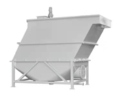
3.1.1. Oil / water separation using a CPI Corrugated Plate Interceptor type separator
The parallel plate oil / water separators - CPI separators - are supplied as prefabricated parts assembled
in the factory. As such, designs vary by manufacturer and the supplier's experience should be used in
sizing and selecting units.
In general, however, the parameters and procedures used for the design of parallel plate separators are the
same as for conventional separators.
The following table shows the design criteria adopted for conventional separators (CPI).
Size of oil particles removed micron ≥50
SS concentration at the inlet mg / l ≤100 - 200
SS concentration at the outlet mg / l ≤50
Specific gravity of oily water kg / m3 910 - 950
Waste water temperature °C 21 - 43
In the case of CPI separators, the perpendicular distance between the plates must be between 2 and 4
cm, and the angle of inclination of the plate with respect to the horizontal must be between 45 and 60
degrees.
The location of the oil / water separator is especially important for parallel plate separators, which
may require frequent cleaning. Removal for cleaning with high pressure cleaning equipment was the
procedure of choice.
For this, provision has been made for setting up a service water network (treated water from the process),
with gate valves and pressurized with a “booster”.
The sediment removal from the separation chamber will be done by installing the gravity pipes and the
installation of a container near this equipment.
The recovered oils will also be drained by gravity to a pumping well to be installed in the STEP. These oils
will be sent back to two existing tanks.
4.1.1. Coagulation-assisted dissolved air flotation – flocculation DAF
In the design of the dissolved air flotation stage, with the introduction of the upstream coagulation
flocculation stages, the following criteria were taken into consideration:
Table 3. Design Criteria for Coagulation-Flocculation Assisted Dissolved Air Flotation
Setting UniT Value Observations
Elimination of O&G and MES
%
> 951. BASES FOR SIZING WORKS AND FACILITIES
1.1. GENERAL CONSIDERATIONS
In this chapter we present a summary of the basic data established for the elaboration of the
project, which constitute the basis for the design of the wastewater treatment plant (now
referred to as STEP).
Thus, in the next paragraphs we again present the design flow rates considered, as well as the
design parameters adopted for the sizing of the STEP (including piping and pumping).
1.1.1. Design flow rates
The STEP will have two (2) parallel treatment lines for the liquid phase. The design flow rate
considered is 5 m 3 / h.
In normal situation, the two lines will operate with a flow rate of 2.5 m3 / h per each line.
Note that the equipment and pipes of each line have been sized for a maximum flow rate of
5.0 m3 / h.
Thus, in a situation where a line is out of service (for reasons of breakdown, maintenance,
etc.), it is possible to treat all of the effluent with a single line running, so as to allow
continuous operation. (24/7, if possible) from the station.
2.1.1. Design pollutant loads
As part of this project, on November 15, 2017, samples of contaminated water from the drain
lines of reservoirs 4A8 and P21, in the TMN and TNIS, respectively, were collected,
upstream of the foot separators (API) of bac.
Samples of contaminated water from the drain lines of reservoirs 4A8 and P21, in the TMN
and TNIS, respectively, were collected, upstream of the foot separators (API) of bac and
based on the results referred to above, together with the reference values collected in the
specialized bibliography, it was possible to define the pollutant loads considered for the
sizing of the STEP equipment. The values adopted are presented in the following table.
Waste water treatment plant
Table 1. Pollutant loads for the design of the treatment plant
Settings Unit
Values
considered
pH 6.5-8
Suspended Solids (MES) mg / l 200
Oils and Greases (O&G) mg / l 300
Chemical Oxygen
Demand (DOC) mg / l 2,200
Biochemical Oxygen Demand mg / l 1,100
It is noted that the color and suspended solids (MES) could not be analyzed, because the samples were
too loaded with oil. For this reason, no suspended solids concentration (MES) value was obtained.
The MES parameter is important for defining the treatment process and, therefore, the type of purification
recommended for contaminated water from purges and manifolds.
Thus, the treatment process has been chosen in a judicious way to allow the removal of MES and allow
fulfillment of the discharge limit values in the natural environment.
On the other hand, it is expected that the concentration of the MES parameter will be quite variable
over time (like the other parameters). Due to the low information of the chemical analyzes for this
parameter, as already mentioned above, an average value of 200 mg / l is considered, which is
considered “normal” for these types of effluents according to the specialized bibliography.
In any case, it will obviously be possible to have real tributary pollutant loads higher or lower than this
value.
The equipment has been sized for the flow and, therefore, if the MES concentration is greater than the
value considered, there will be greater production of sediment in the container (the emptying
frequency will be greater) and vice versa.
It will depend, therefore, on the actual values of tributary MES (and other parameters), and, only with
the exploration experience of the STEP, will it be possible to adjust the treatment for the optimal
situation.
In conclusion: the STEP must be continuously monitored from the start of exploration. For such, we
recommend sampling the effluents, with a minimum weekly frequency, of the main parameters: DQO,
DBO5, O&G and MES. Sampling should be done at least at two points: upstream of the STEP (in the
Buffer Tank) and at the outlet of the STEP.
3.1.1. Oil / water separation using a CPI Corrugated Plate Interceptor type separator
The parallel plate oil / water separators - CPI separators - are supplied as prefabricated parts assembled
in the factory. As such, designs vary by manufacturer and the supplier's experience should be used in
sizing and selecting units.
In general, however, the parameters and procedures used for the design of parallel plate separators are the
same as for conventional separators.
The following table shows the design criteria adopted for conventional separators (CPI).
Table 2. Design criteria for conventional separators (CPI)
Setting Unity Value
Removal of emulsified oil
%
20 - 50
Reynolds number
-
<0.5
Length / width ratio
-
5: 1
Depth / width ratio
- 0.3-0.5
Width
m
ft
0.90
Depth
M
ft
Tray spacing
mm
inch
Slope of the plateaus
°
45-90
Climbing speed regulated by Stokes'
law
cm / s
≤1.5
Horizontal speed
m
ft
0.90
3
Size of oil particles removed micron ≥50
SS concentration at the inlet mg / l ≤100 - 200
SS concentration at the outlet mg / l ≤50
Specific gravity of oily water kg / m3 910 - 950
Waste water temperature °C 21 - 43
In the case of CPI separators, the perpendicular distance between the plates must be between 2 and 4
cm, and the angle of inclination of the plate with respect to the horizontal must be between 45 and 60
degrees.
The location of the oil / water separator is especially important for parallel plate separators, which
may require frequent cleaning. Removal for cleaning with high pressure cleaning equipment was the
procedure of choice.
For this, provision has been made for setting up a service water network (treated water from the process),
with gate valves and pressurized with a “booster”.
The sediment removal from the separation chamber will be done by installing the gravity pipes and the
installation of a container near this equipment.
The recovered oils will also be drained by gravity to a pumping well to be installed in the STEP. These oils
will be sent back to two existing tanks.
4.1.1. Coagulation-assisted dissolved air flotation – flocculation DAF
In the design of the dissolved air flotation stage, with the introduction of the upstream coagulation
flocculation stages, the following criteria were taken into consideration:
Table 3. Design Criteria for Coagulation-Flocculation Assisted Dissolved Air Flotation
Setting UniT Value Observations
Elimination of O&G and MES
%
> 95
-
Hydraulic loading rate for rectangular units
m3 / m2 h 3.67 - 7.33
including the
recycling stream
Hydraulic loading rate for circular units
m3 / m2 h 2.44 - 4.89
including the
recycling stream
Recycling stream
%
20 -33 Forward flow
concentration of oil and MES at the inlet
mg / l ≤500
Air system operating pressure
psi 40-60
Coagulation time s 30 - 120
Flocculation time min 5-15
Flotation time min 20 -30
*When used as a
primary
sedimentation.
*When the
thickening is higher
It will need to have a
longer retention time.
The aeration system will only operate when the concentration of O&G and MES is less than 1000 mg
/ l, in each unit.
5.1.1. Biological treatment and solid-liquid separation in MBR
In the design of the biological treatment step and the solid-liquid membrane separation (MBR), the
following criteria were taken into consideration:
Table 4. Design criteria for biological treatment in MBR reactors
Setting Unit Value Observations
Porosity of
membranes
(microfiltration)
% 0.20 -
Porosity reached
(ultrafiltration)
μm 0.01
Due to the formation of the
layer of proteins and
cellular materials around the
membranes the filtration
reaches the gamma of an
ultrafiltration
Contact area per unit
volume
m2 / m3 165
for symmetrical flat
membranes
Concentration of
solids
g / l 15-20
conventional systems normal
values are 3 - 5 g / l
Sludge concentration g / l 10 -15
conventional system normal
values are 3-4 g / l
Recirculation % 50 -
Due to the formation of the layer of proteins and cellular materials around the membranes
and the occurrence of ultrafiltration, the result is the retention of virtually all bacteria, viruses
and solid particles, including the colloidal material that are disposed of in the sludge.
6.1.1. Quality objectives: Limit values for effluent discharge
The limit values for discharges of industrial liquid effluents, to be taken into account, defined
by Executive Decree are presented in the below table.
LIMIT VALUES OF INDUSTRIAL LIQUID EFFLUENT DISCHARGE PARAMETERS
SETTINGS Unit VALUES
VALUES
TOLERANCES
LMTES
ANCONNEES
FACILITIES
1 Temperature °C 30 30
2 pH 6.5 - 8.5 6.5 - 8.5
3 MES mg / l 35 40
4 Kjeldahl Nitrogen 30 40
5 Total phosphorus 10 15
6 COD 120 130
7 DBO5 35 40
8 Aluminum 3 5
9
Bio accumulative toxic
substances
0.005 0.01
10 Cyanides 0.1 0.15
11 Fluorine and components 15 20
12 Phenol index 0.3 0.5
13 Total hydrocarbons 10 15
14 Oils and greases 20 30
15 Cadmium 0.2 0.25
16 Total copper 0.5 1
17 Total mercury 0.01 0.05
18 Total lead 0.5 0.75
19 Total Chrome 0.5 0.75
20 Total tin 2 2.5
21 Manganese 1 1.5
22 Total nickel 0.5 0.75
23 Zinc total 3 5
24 Iron 3 5
25 Chlorinated organic compounds 5 7
PH: Hydrogen potential
DBO5: Biological oxygen demand for a period of five (5) days
COD: Chemical Oxygen Demand MES:
Suspended matter
7.1.1. expected Characteristics of contaminated water tributaries to the STEP
As indicated in Table 1, these will be the values taken into account of the effluent entering the
STEP, for the design of the treatment system and the respective sizing of the equipment.
Thus, and taking into account the limit values presented in Table 5, the overall purification
efficiency of the station is estimated for each parameter, which is presented in the following
table.
Table 5. Expected overall yield for the treatment
Settings Yield (%)
Suspended Materials (MES) >95
Oils and Greases (O&G) >95
Chemical Oxygen Demand (COD) 94.5
Biochemical Oxygen Demand (DBO5) 96.8
Hydrocarbon C10-C40 >95
2. DETAILED DESCRIPTION
2.1. SITE-
Hydraulic loading rate for rectangular units
m3 / m2 h 3.67 - 7.33
including the
recycling stream
Hydraulic loading rate for circular units
m3 / m2 h 2.44 - 4.89
including the
recycling stream
Recycling stream
%20 -33 Forward flow
concentration of oil and MES at the inlet
mg / l ≤500
Air system operating pressure
psi 40-60
Coagulation time s 30 - 120
Flocculation time min 5-15
Flotation time min 20 -30
*When used as a
primary
sedimentation.
*When the
thickening is higher
It will need to have a
longer retention time.
The aeration system will only operate when the concentration of O&G and MES is less than 1000 mg
/ l, in each unit.
5.1.1. Biological treatment and solid-liquid separation in MBR
In the design of the biological treatment step and the solid-liquid membrane separation (MBR), the
following criteria were taken into consideration:
Table 4. Design criteria for biological treatment in MBR reactors
Setting Unit Value Observations
Porosity of
membranes
(microfiltration)
% 0.20 -
Porosity reached
(ultrafiltration)
μm 0.01
Due to the formation of the
layer of proteins and
cellular materials around the
membranes the filtration
reaches the gamma of an
ultrafiltration
Contact area per unit
volume
m2 / m3 165
for symmetrical flat
membranes
Concentration of
solids
g / l 15-20
conventional systems normal
values are 3 - 5 g / l
Sludge concentration g / l 10 -15
conventional system normal
values are 3-4 g / l
Recirculation % 50 -
Due to the formation of the layer of proteins and cellular materials around the membranes
and the occurrence of ultrafiltration, the result is the retention of virtually all bacteria, viruses
and solid particles, including the colloidal material that are disposed of in the sludge.
6.1.1. Quality objectives: Limit values for effluent discharge
The limit values for discharges of industrial liquid effluents, to be taken into account, defined
by Executive Decree are presented in the below table.
LIMIT VALUES OF INDUSTRIAL LIQUID EFFLUENT DISCHARGE PARAMETERS
SETTINGS Unit VALUES
VALUES
TOLERANCES
LMTES
ANCONNEES
FACILITIES
1 Temperature °C 30 30
2 pH 6.5 - 8.5 6.5 - 8.5
3 MES mg / l 35 40
4 Kjeldahl Nitrogen 30 40
5 Total phosphorus 10 15
6 COD 120 130
7 DBO5 35 40
8 Aluminum 3 5
9
Bio accumulative toxic
substances
0.005 0.01
10 Cyanides 0.1 0.15
11 Fluorine and components 15 20
12 Phenol index 0.3 0.5
13 Total hydrocarbons 10 15
14 Oils and greases 20 30
15 Cadmium 0.2 0.25
16 Total copper 0.5 1
17 Total mercury 0.01 0.05
18 Total lead 0.5 0.75
19 Total Chrome 0.5 0.75
20 Total tin 2 2.5
21 Manganese 1 1.5
22 Total nickel 0.5 0.75
23 Zinc total 3 5
24 Iron 3 5
25 Chlorinated organic compounds 5 7
PH: Hydrogen potential
DBO5: Biological oxygen demand for a period of five (5) days
COD: Chemical Oxygen Demand MES:
Suspended matter
7.1.1. expected Characteristics of contaminated water tributaries to the STEP
As indicated in Table 1, these will be the values taken into account of the effluent entering the
STEP, for the design of the treatment system and the respective sizing of the equipment.
Thus, and taking into account the limit values presented in Table 5, the overall purification
efficiency of the station is estimated for each parameter, which is presented in the following
table.
Table 5. Expected overall yield for the treatment
Settings Yield (%)
Suspended Materials (MES) >95
Oils and Greases (O&G) >95
Chemical Oxygen Demand (COD) 94.5
Biochemical Oxygen Demand (DBO5) 96.8
Hydrocarbon C10-C40 >95
